
 
     |
| ECM questions, sensors, TPS and MAP (Page 1/5) |

|
fierobear
|
FEB 21, 03:17 PM
|
|
I'm having issues, suddenly, with my 88GT. Two of the sensors are reading lower voltage than they should. I have an AutoXRay scanner to see the sensor data in real time when I'm doing diagnostics. I had a code for TPS voltage high (code 21, I think) and the car ran like s***. Very rough running, stalling. I didn't see high voltage on the scanner. I replaced the TPS with brand new from Rock Auto. I got a sensor tester from eBay and tested it, no problems. Put it on the car, still running rough and now throws a code for TPS voltage LOW. On the scanner, it returns .19 volts at idle (code sets below .2v for more than 2 seconds) and .89v at WOT (well, at about 4000 rpm). It should be more than .2v and closer to 5v at high throttle. So now I'm thinking electrical issue, high resistance, alternator/regulator, etc.
The scanner shows system voltage seen by the ECM pretty steady (+/- .2v) at 14v. All other sensors (except MAP) appear to be in their proper operating range. The wiring connector or adjacent wiring might be worn or developing high resistance. I assume that could cause incorrect voltage? Is it possible there is a small enough problem with the ECM to cause two sensors to be out of range, but everything else is fine? Bad capacitor?
The MAP sensor tests good on the tester, and doesn't throw a code. But it is also not returning enough voltage to the ECM (doesn't throw a code). Tested with good used and a new part.
As far as ECMs go, it appears there are only 5 types of ECMs, 3 for 4 cylinder, and 2 for V6...
85........1226869
86-88...1227170
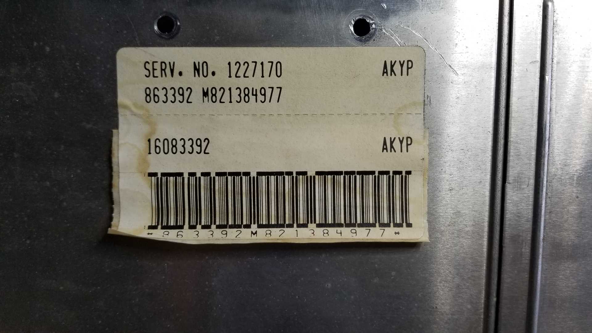
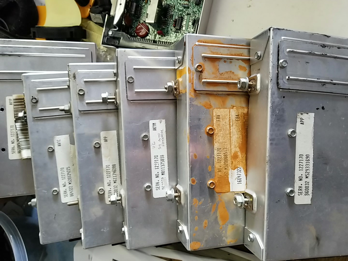
I have a stack of ECMs with part number 1227170, but there several other numbers and letter codes that are different. I had a note scribbled on one of them saying "federal", probably a different ECM for California? There are only two part numbers in the 22P book, with no difference between auto and manual transmissions? Is there an ECM application guide somewhere?
|
|
|
|
FieroJimmy
|
FEB 21, 07:32 PM
|
|
| quote | Originally posted by fierobear:
I'm having issues, suddenly, with my 88GT. Two of the sensors are reading lower voltage than they should. I have an AutoXRay scanner to see the sensor data in real time when I'm doing diagnostics. I had a code for TPS voltage high (code 21, I think) and the car ran like s***. Very rough running, stalling. I didn't see high voltage on the scanner. I replaced the TPS with brand new from Rock Auto. I got a sensor tester from eBay and tested it, no problems. Put it on the car, still running rough and now throws a code for TPS voltage LOW. On the scanner, it returns .19 volts at idle (code sets below .2v for more than 2 seconds) and .89v at WOT (well, at about 4000 rpm). It should be more than .2v and closer to 5v at high throttle. So now I'm thinking electrical issue, high resistance, alternator/regulator, etc.
The scanner shows system voltage seen by the ECM pretty steady (+/- .2v) at 14v. All other sensors (except MAP) appear to be in their proper operating range. The wiring connector or adjacent wiring might be worn or developing high resistance. I assume that could cause incorrect voltage? Is it possible there is a small enough problem with the ECM to cause two sensors to be out of range, but everything else is fine? Bad capacitor?
The MAP sensor tests good on the tester, and doesn't throw a code. But it is also not returning enough voltage to the ECM (doesn't throw a code). Tested with good used and a new part.
|
|
The first thing I would do is put a multimeter on the sensors and see if you have the full +5v at the sensors. If you've got a failed regulator in the ECM, you might not have the full +5v out of the ECM. The next thing is to jump the signal circuit of each sensor to the +5v, and the sensor ground alternately, while monitoring your scantool data. If the ECM sees (and reports) +5v and 0v, your wiring is all good. I suspect you'll find you don't have the full +5v. The MAP and TPS are both fed by circuit 416, a gray wire out of C14 from the ECM.
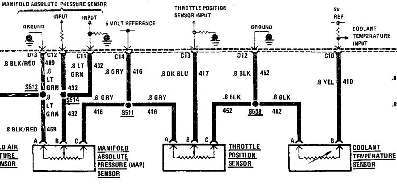
I included the CTS in this pic to show that it is on a different +5v circuit out of the ECM. I don't know if there are more than one actual 5v regulator in the ECM, or if they all share a single regulator.
| quote | Originally posted by fierobear:
As far as ECMs go, it appears there are only 5 types of ECMs, 3 for 4 cylinder, and 2 for V6...
85........1226869
86-88...1227170
I have a stack of ECMs with part number 1227170, but there several other numbers and letter codes that are different. I had a note scribbled on one of them saying "federal", probably a different ECM for California? There are only two part numbers in the 22P book, with no difference between auto and manual transmissions? Is there an ECM application guide somewhere?
|
|
The AKYP is the broadcast code for the PROM calibration. The part number 1227170 is for the computer itself, with no PROM. There are a VAST number of possible broadcast codes, with different calibrations for Auto vs Manual, Fed emissions vs California, 4.10 vs 3.65, and so on. I'm not aware of a compiled list for Fiero broadcast codes.
|
|

|
theogre
|
FEB 21, 08:29 PM
|
|
Multiple sensor w/ problems first check have 5v and/or ground from ECM.
Check at sensors and at ECM because maybe iffy wires not iffy ECM.
TPS etc have 5v and/or ground directly from ECM.
Sensor Ground wires to engine should be near zero volts and near zero Ω. Do Not use Ω meter on other ECM wires as most Ω meters can fry the ECM.
5v to sensor ground wires should be 5v ± 0.3v max. Do Not measure 5v to block/frame. Likely won't damage but have errors no matter how careful you test to block etc.
(If you have a analog meter or Digital w/ Rel button is better. Both allow you to cancel Ω for probe wire etc.)
But watch ICM and O2 because the "grounds" for them are "fake Grounds" that only see why when have schematics and know what you're reading across several pages or worse across several documents. Do Not use Ω meter.
ICM fake ground is in my Cave, Ground "Myth" notes O2 fake ground is tan wire to block where trans bell mounts.
Check/fix/clean all ground ends bolted to engine @ minimum. G202 too since have console out to look at ECM. Is on tunnel below ECM.
Clean and coat w/ silicon or brake grease.------------------
Dr. Ian Malcolm: Yeah, but your scientists were so preoccupied with whether or not they could, they didn't stop to think if they should.
(Jurassic Park)
The Ogre's Fiero Cave
|
|
|
|
Raydar
|
FEB 23, 01:06 AM
|
|
|
|
|
theogre
|
FEB 23, 03:27 AM
|
|
Is just 1 page of Ludis' site w/ a lot more then that.
Site shut down or moved then died in last few years. Don't no if any have copies except archive.org and that's missing some pages/images
|
|
|
|
Raydar
|
FEB 23, 10:34 AM
|
|
The conversation was regarding Fiero ECMs and broadcast codes.
The other stuff on those pages seems to be non-Fiero - or just common to many other platforms.
In any event, maybe the tables will provide enough info to be useful.[This message has been edited by Raydar (edited 02-23-2020).]
|
|
|
|
fierobear
|
FEB 23, 03:13 PM
|
|
Excellent, thanks! I remembered Ludis’s page, but am surprised it was still up.
If that data is complete, the only transaxle ratio PROMS appear to be for early 4 speed transaxles.
|
|
|
|
FieroJimmy
|
FEB 23, 04:23 PM
|
|
| quote | Originally posted by fierobear:
Excellent, thanks! I remembered Ludis’s page, but am surprised it was still up.
If that data is complete, the only transaxle ratio PROMS appear to be for early 4 speed transaxles.
|
|
All of the Isuzus and all of the Getrags only had one ratio option (in Fieros, I know the Isuzu could be had with a 4.11 final in some of the Geo applications).
|
|
|
|
Raydar
|
FEB 23, 06:17 PM
|
|
| quote | Originally posted by fierobear:
Excellent, thanks! I remembered Ludis’s page, but am surprised it was still up.
If that data is complete, the only transaxle ratio PROMS appear to be for early 4 speed transaxles.
|
|
As Jimmy posted, all of the Fiero Getrags had the same FDR. And all of the V6 4 speeds had the same ratio.
The only real variable was tire size, and that wouldn't likely affect any functionality. If anything, it probably affected the timing of the "upshift" light. Which is probably a big deal in California, considering how they are. 
Edit - It would appear that all V6 automatic FDRs were either 3.06 or 3.33. 86s seem to have used both. I don't know if the ratio change had anything to do with model (SE vs GT) or if it was a running change done to all cars, after a certain date.[This message has been edited by Raydar (edited 02-23-2020).]
|
|
|
|
fierobear
|
FEB 24, 01:07 PM
|
|
Looking at the ECMs I have as spares (as seen in the picture up thread), the closest one I have is the APP ECM, for the 86-87 5-speed CA chip. I also have a 5 speed Formula sitting around, so I should be able to “borrow” that ECM for a simple test. My scanner shows the Formula sensors look more normal, although the TPS didn’t show voltage anywhere close to 5v at 4000rpm. I don’t think I’ve ever seen any of my Fieros show that much voltage.
Anyway, assuming for the moment that the 5v reference circuit in the current ECM is faulty, would the problem be only an internal failure of the ECM, or could the failure be caused by the wiring between the ECM and sensors?
|
|
|
|