
 
     |
| The White Bug (Page 1/46) |

|
pmbrunelle
|
JAN 03, 10:14 AM
|
|
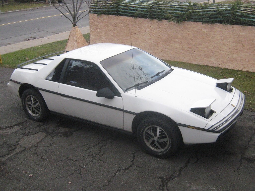
I purchased this Fiero in December 2016. A mostly bone-stock 1985 SE, with 53k miles.
Minimal rust and fairly decent paint; should look good enough (by my standard) with a wash and wax, and some minor fixes (dew wipes, headliner, that sort of thing).
It came with the automatic transmission, but that's fine; transmissions can be changed.
Half an hour into the 2 hour drive home, the 2.8 started knocking; the car had to be towed.
The engine's death signaled to me: PROJECT TIME!
Time to do the turbo project I've always wanted for a Fiero, get rid of the slushbox, and fix the "incidentals" while I'm at it.
Now that I've been working on the car a little while, I guess it's a good time to make a project thread.
|
|
|
|
pmbrunelle
|
JAN 03, 10:42 AM
|
|
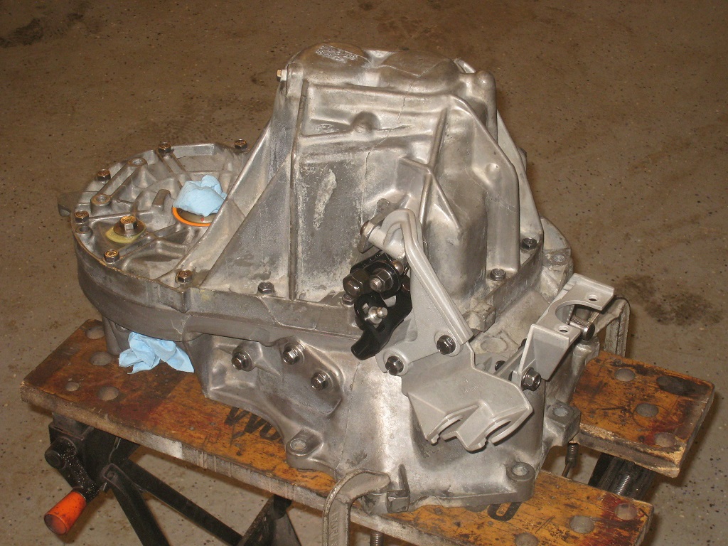
For the transmission, I decided to go with the Muncie 4-speed. Since this is my first real car project, I wanted something simple for a first-timer... I didn't want to pull a speed gear and have a bunch of needles fall all over the place.
I don't know how the Fiero Muncie will cope with more torque than stock, but Archie sold V8 kits to work with the stock transmission, so... I'll see what happens.
I made sure to use the ribbed case, not the smooth case.
Anyway, so here I am scavenging pieces from three Muncies, in order to make myself a good one:
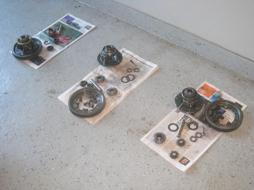
I got a few brand-new parts to supplement the scavenged stuff.
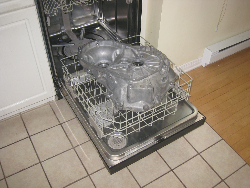
Here, I clean the transmission case:
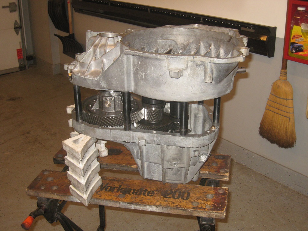
Closing up the transmission. From my collection of scavenged shims, I was able to shim the tapered roller bearings without having to buy or modify any shims.
I didn't have the required shifter shaft selective washer on hand, so I just machined the shift shaft to compensate.
I decided to use the complete 1984 M19 gearset.
I thought about using the 3.31/1.95 1st/2nd from the M17, since they're closer together than the 3.53/1.95 1st/2nd of the M19.
However, I wanted the deep 1st gear reduction.
My previous Fiero had an Isuzu transmission, and I learned to deal with the wide 1st/2nd gap. The M19 is no worse than what I've become used to.
All buttoned up:
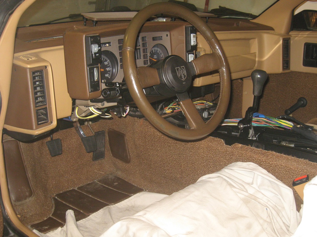
Of course, an automatic car needs more than just a transmission! It needs a 3rd pedal:
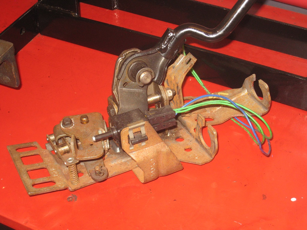
And a shifter assembly. Before cleanup:
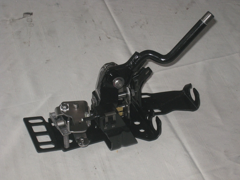
After cleanup:
|
|
|
|
Spadesluck
|
JAN 03, 11:08 AM
|
|
|
I did that very same thing to my shifter. It looked terrible before rebuilding and painting it.
|
|
|
|
pmbrunelle
|
JAN 03, 11:16 AM
|
|
The reverse interlock roller was actually seized. I worked it free, but I don't think it made a difference that could be felt by the driver.
Having the shifter cleaned up, it's like driving a freshly washed car with shiny paint. Even though it makes no functional difference, it's still more fun to drive. It's psychological.
|
|
|
|
BadNewsBrendan
|
JAN 03, 11:34 AM
|
|
Wonder if I can convince my roommate to let me do the same thing with our dishwasher 
|
|
|
|
pmbrunelle
|
JAN 03, 11:47 AM
|
|
Well you clean off the majority of the gunk before sticking it in the dishwasher. That's just for the final touch of clean.
Then, you put the auto parts in the dishwasher without telling anyone; it's easier to ask for forgiveness than to ask for permission.
You can explain that whatever grime remains on the parts is no worse than last night's chicken wing grease that's slathered over the dish plates.
|
|
|
|
pmbrunelle
|
JAN 03, 12:10 PM
|
|
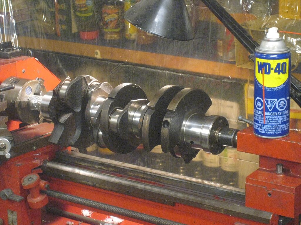
For the engine, my friend gave me a 3.1 from a Chevrolet Beretta. Aside from the additional ~300 cc of displacement, I wanted it since it comes with a crankshaft position sensor.
The crankshaft position sensor provides the best possible angle information to the ECU, compared to using a distributor with slack in the timing chain.
Driving manners are important to me; for the ECU to do a good job, all its inputs have to be clean.
This is the setup I used to polish the #981 crankshaft's main journals.
I used the shoelace method for the throws.
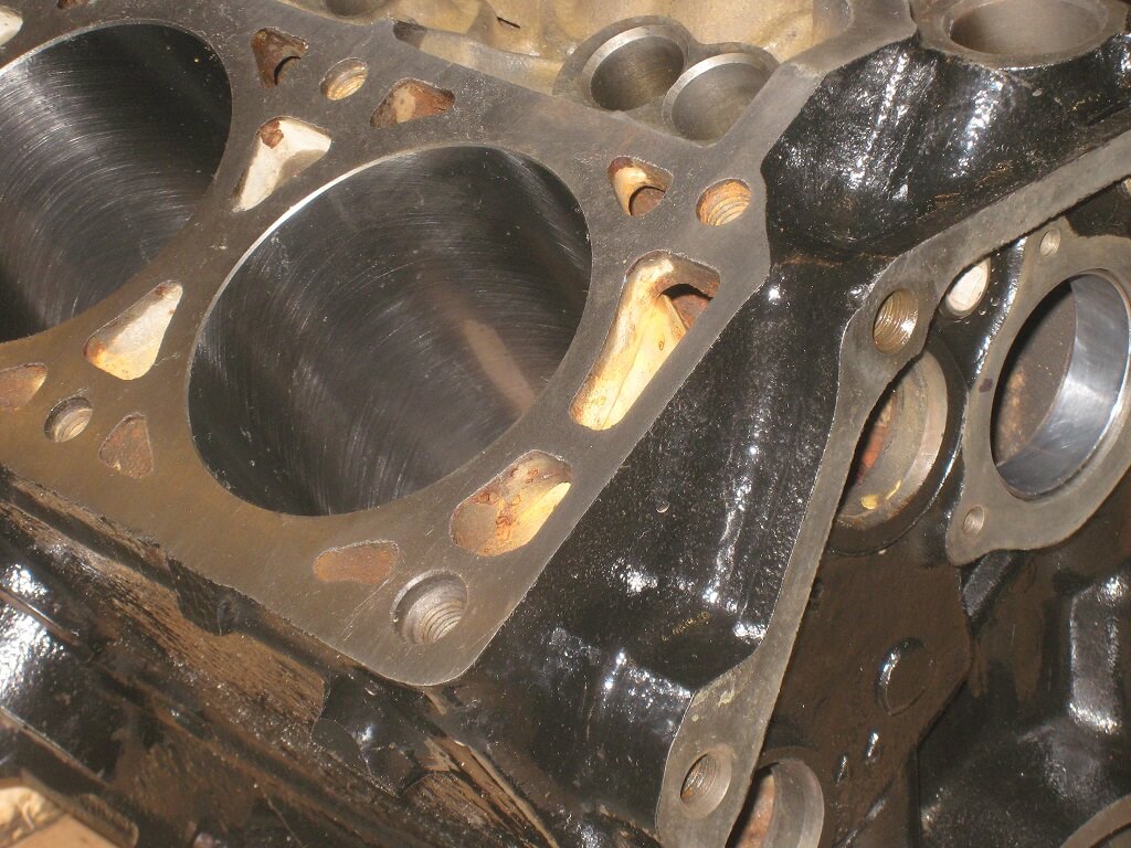
I had the block decked to remove pitting that would prevent the head gasket from sealing, particularly since a turbo engine has more cylinder pressure than stock. I'm using the Fel-Pro MLS head gaskets.
I got hypereutectic dished pistons, 0.75 mm over.
The machinist bored the cylinders to 0.80 mm over, to give me a little more piston-to-wall clearance. From the turbo engine's extra heat, more clearance is needed to avoid seizing the piston in the bore.
I also filed the piston rings to have larger-than usual gaps, again to deal with the heat.
The displacement is 3192 cc with a compression ratio of 7.4.
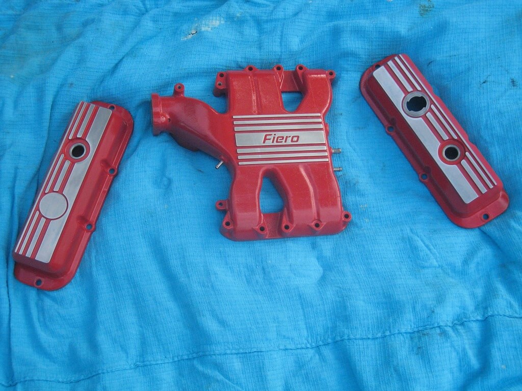
The obligatory top end cover painting. I used single-stage DuPont (Axalta nowadays?) Nason paint.
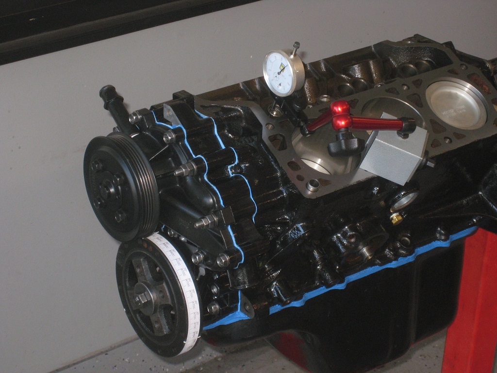
Here I am inspecting the camshaft's lobe lift as I rotate the crankshaft.
The camshaft is a hydraulic flat tappet cam from Crower. I told them about my turbo build, and they specified it for me. It has a 114° LSA.
A Cloyes double-roller chain drives the camshaft.
I installed a high-volume oil pump.
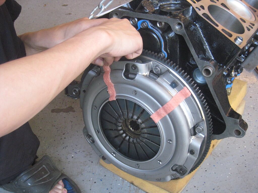
The clutch is the RAM 9.75" HD unit from the Fiero Store. I know that some people use it with the Cadillac 4.9, so it should hold a decent amount of torque.
Eventually, as I crank up the boost pressure, the clutch might slip. Not a big deal, I'll change the clutch if there's an issue.
Making sure that the pressure plate won't rub the inside of the bellhousing:
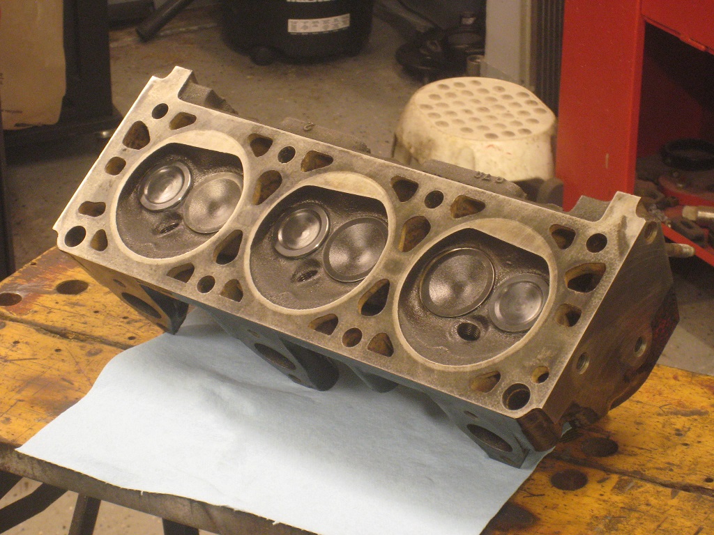
Cylinder heads are stock. I didn't port the heads, as I didn't want to risk dinging the valve seats and needing a valve job (more expenditures).
I replaced the exhaust valves (pitted contact faces), and lapped all 12 valves.
Valve springs are new; they came with the camshaft.
I have 1.52 roller-tipped rockers for these heads.
Long block (mostly) complete:
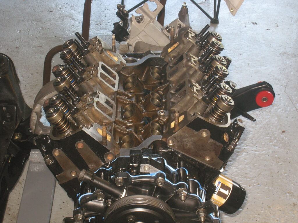 [This message has been edited by pmbrunelle (edited 01-03-2019).]
|
|
|
|
pmbrunelle
|
JAN 03, 12:42 PM
|
|
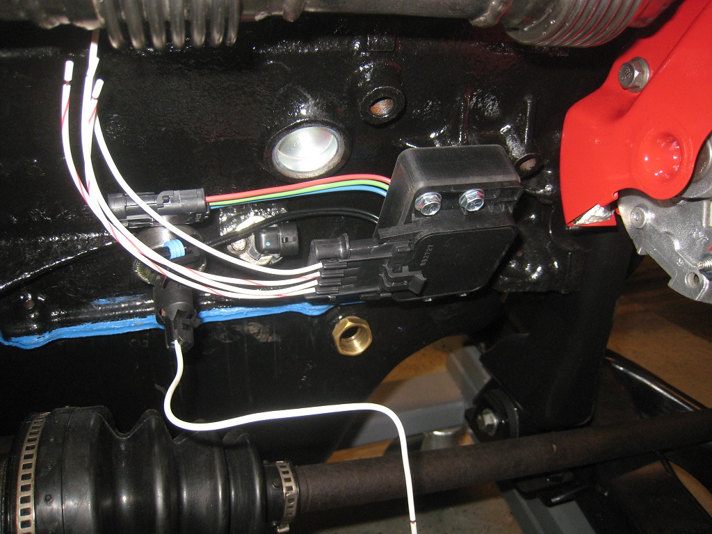
In a standard 90s GM setup, the crankshaft position sensor is wired to the DIS brick.
I don't want a DIS; I want my Fiero to have the classic distributor look. Hence, in this setup, the crank sensor is read "directly" by the ECU; no DIS brick in between.
I did, however, make a circuit to convert the crank sensor's weak analog signal into a robust digital signal.
It uses a Maxim MAX9924 integrated circuit to do the job.
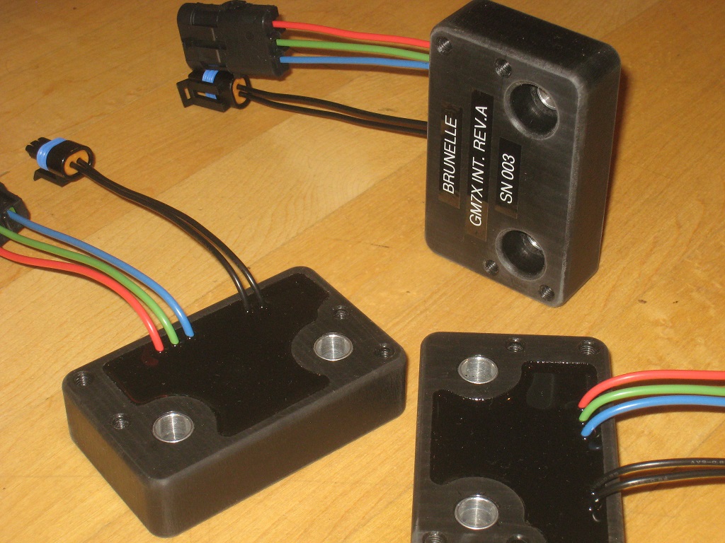
The case is made from CNC-machined nylon 6/6.
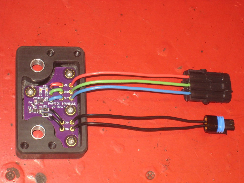
The converter circuit is located as close as possible to the crank sensor, to reduce the chance of picking up noise in the leads.
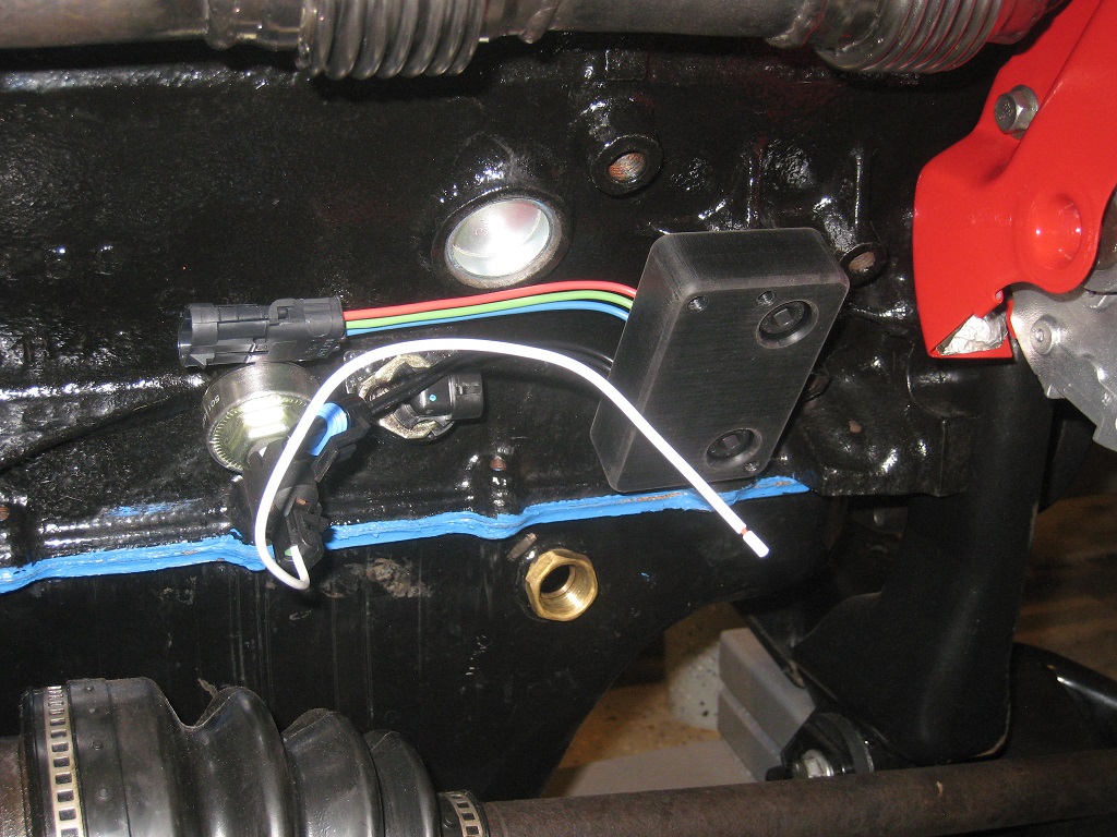
The converter also provides threaded mounting holes for the GM knock sensor module, which goes right on top of it:
The modules are potted in urethane for sealing out the elements.
I made three of them, since if the module ever dies, I can't just walk into NAPA and get a replacement.
I left one module not potted; in case I discover a design flaw that led to the failure of the first two, I'd be able to make some changes before potting and installation into the car.
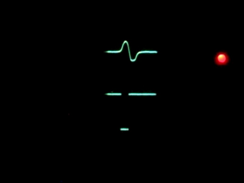
Here is a test I did, turning over the engine with the starter.
A tooth on the crankshaft is passing by the crankshaft sensor at the moment of this oscilloscope capture.
Top trace: analog signal from crankshaft position sensor
Bottom trace: digital signal sent to ECU
 [This message has been edited by pmbrunelle (edited 01-03-2019).]
|
|
|
|
pmbrunelle
|
JAN 03, 01:01 PM
|
|
Since the battery tray was falling apart, I decided to replace it with a new Fiero Store unit.
However, the root of (I think) the battery tray rust problem, common to many Fieros, is that the battery acid overflows and leaks onto the metal below.
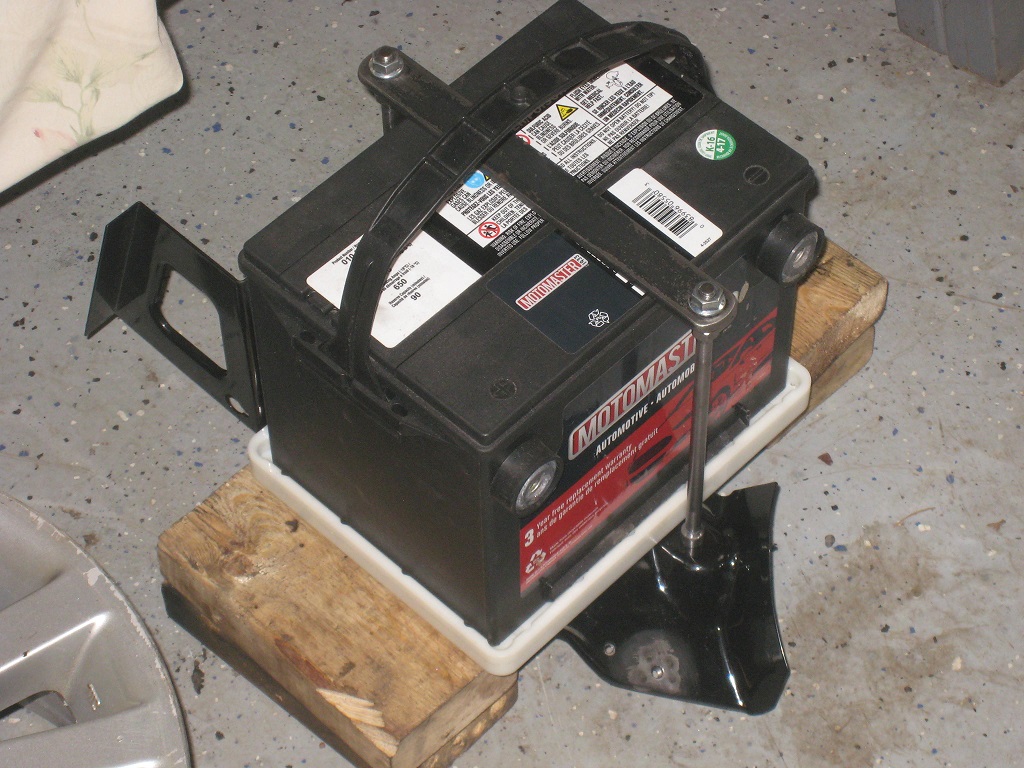
Therefore, I decided to make a polypropylene battery tray. It is designed to channel any liquids to a drain fitting, on which a drain line can be installed to direct any liquids to the ground.
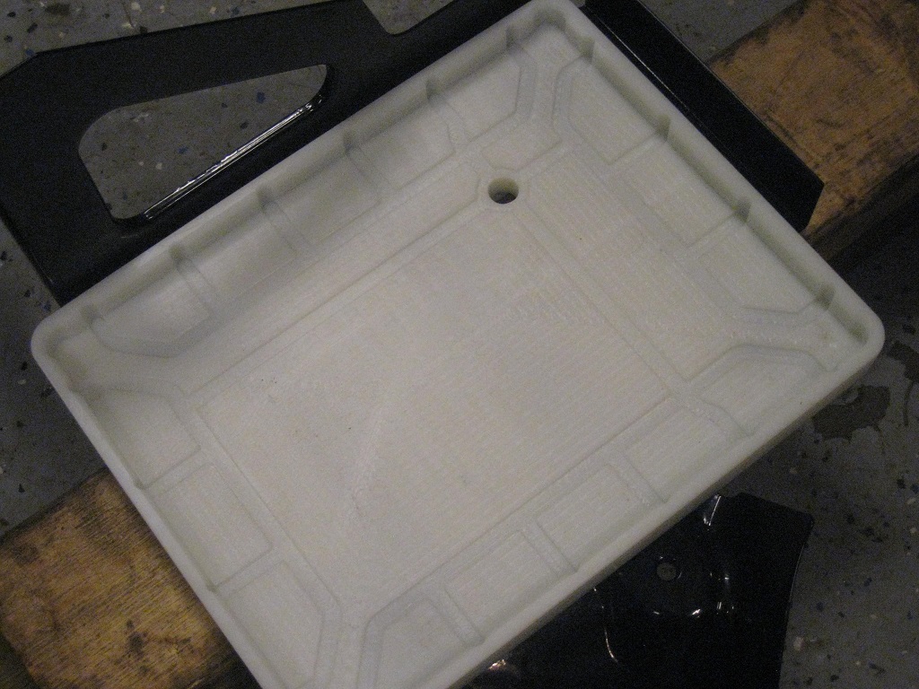
I also didn't like factory method of gripping the battery by the two lips at the bottom. I don't find the factory method secure enough, especially when the rust bug bites.
So, I decided to hold down the battery more positively, with a flatbar over the top and rods keeping the flatbar in its place.
|
|
|
|
pmbrunelle
|
JAN 03, 01:20 PM
|
|
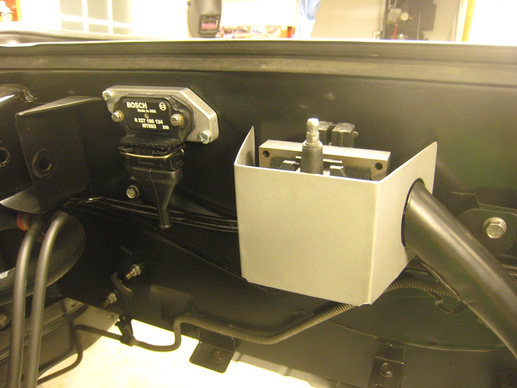
Since I want to put the turbo above the transmission, I moved the ignition coil over to the trunk wall to get it away from the heat.
As this engine won't have a working HEI module to fire the ignition coil, I installed a Bosch ignition module. This particular Bosch module came from an 80s Volvo.
In the Volvo application, the module is mounted on its own heatsink, which is then screwed onto the fender. I decided to use this entire module + heatsink assembly.
There were other heatsinks used with Bosch modules, but I liked the shape of this one for my Fiero.
 [This message has been edited by pmbrunelle (edited 01-03-2019).]
|
|
|
|